Metal
Garden Cart

Instructions

Easy to follow product instructions for your metal utility garden cart with removable mat
(Model: RP-GEMC)

Instructions

Metal Utility Garden Cart

Easy to follow product instructions for your metal utility garden cart with removable mat
(Model: RP-GEMC)

Instructions

Metal Utility Garden Cart

Easy to follow product instructions for your metal utility garden cart with removable mat
(Model: RP-GEMC)

Congratulations on your purchase of a Ray Padula metal garden cart. Follow these instructions to properly assemble your RP-GEMC cart. The complete instruction manual can also be downloaded below. Be sure to always follow all safety information and warnings before assembling and using your cart.

Congratulations on your purchase of a Ray Padula metal garden cart. Follow these instructions to properly assemble your RP-GEMC cart. The complete instruction manual can also be downloaded below. Be sure to always follow all safety information and warnings before assembling and using your cart.

Congratulations on your purchase of a Ray Padula metal garden cart. Follow these instructions to properly assemble your RP-GEMC cart. The complete instruction manual can also be downloaded below. Be sure to always follow all safety information and warnings before assembling and using your cart.

Safety Information & Warnings

Please read, understand and follow all instructions and warnings in the user manual before using your garden cart.

Safety Information & Warnings

Please read, understand and follow all instructions and warnings in the user manual before using your garden cart.

Safety Information & Warnings

Please read, understand and follow all instructions and warnings in the user manual before using your garden cart.

.

Do NOT tow this cart on steep hills.
Do NOT tow this cart faster than 2 mph.
While towing, make slow turns to avoid damage to the cart and its contents.
Do NOT exceed 30 PSI when inflating the tires as damage to the tires and/or personal injury could result.
Do NOT load this cart with more than 500 lbs (225 kgs) of contents.
This cart is NOT to be used for transporting people or animals, at any time.
This cart is NOT to be used for highway use.
Always distribute the load evenly across the surface of the cart bed.
If any part of this cart becomes broken, damaged, or misplaced, do NOT use the cart until a replacement part has been obtained and replaced.
Do NOT operate this cart on surfaces, or roll over objects that are sharp, jagged or could cause damage to the tires or tubes.
Use only a hand-held air pump to inflate tires (if necessary).

Preparation

Before beginning assembly of this product, make sure all parts are present. Compare parts with package contents listed below. If any part is missing or damaged, do not attempt to assemble this product. Contact us for replacement parts. The estimated assembly time of this cart is 12-15 minutes.

Tools Needed

The following tools are needed for proper assembly (not included).

Tools Needed

The following tools are needed for proper assembly (not included).

Tools Needed

The following tools are needed for proper assembly (not included).

• Adjustable wrench

• 1/2 in. ratchet

• Pliers

• Phillips head screwdriver

Optional Tools (not required for assembly)
• Handheld air pump
• Tire pressure gauge

• Adjustable wrench

• 1/2 in. ratchet

• Pliers

• Phillips head screwdriver

Optional Tools (not required for assembly)
• Handheld air pump
• Tire pressure gauge

• Adjustable wrench
• 1/2 in. ratchet
• Pliers
• Phillips head screwdriver

Optional Tools (not required for assembly)
• Handheld air pump
• Tire pressure gauge

Package Contents & Parts

Make sure all parts and components are present before assembling your cart.

Package Contents & Parts

Make sure all parts and components are present before assembling your cart.

Package Contents & Parts

Make sure all parts and components are present before assembling your cart.

Parts List

A. Cart Bed- QTY: 1
F. Wheels - QTY: 4
G. Rear Axle Support - QTY: 1
H. Left Rear Axle Brace - QTY: 1
I. Right Rear Axle Brace- QTY: 1
J. Front Axle Support - QTY: 1
K. Center Front Axle Brace - QTY: 1
L. Yoke - QTY: 4
M. Steering Link Connector- QTY: 4
N. Plastic coupling - QTY: 1
O. Pull Handle - QTY: 1
P. Removable Rubber Mat - QTY: 1

Parts List
A. Cart Bed- QTY: 1
F. Wheels - QTY: 4
G. Rear Axle Support - QTY: 1
H. Left Rear Axle Brace - QTY: 1
I. Right Rear Axle Brace- QTY: 1
J. Front Axle Support - QTY: 1
K. Center Front Axle Brace - QTY: 1
L. Yoke - QTY: 4
M. Steering Link Connector- QTY: 4
N. Plastic coupling - QTY: 1
O. Pull Handle - QTY: 1
P. Removable Rubber Mat - QTY: 1

Hardware List

CC. Large Lock Pins- QTY: 1
FF. 8 mm. Washer - QTY: 8
GG. 8 mm. Nuts with Lock Inserts - QTY: 7
HH. 16 mm. Washers QTY: 4
II. Carriage Support Bolts (used with parts FF and GG) - QTY: 7 (these are already installed on your cart)
JJ. Small Columnar Pin - QTY: 1
L. Cotter Pin - QTY: 7 (3 are already installed on your cart)
RR. 16 mm. Small Ring Washer - QTY: 2
MM. Retainer Washer - QTY: 1
NN. Short Steering Bolts (used with parts PP and QQ) - QTY: 3
OO. Long Steering Bolt (used with parts PP and QQ) - QTY: 1
PP. 6 mm. Lock Nuts - QTY: 4
QQ. 6 mm. Washers - QTY: 4
KK. Axel Cap - QTY: 2

Hardware List

CC. Large Lock Pins- QTY: 1

FF. 8 mm. Washer - QTY: 8

GG. 8 mm. Nuts with Lock Inserts - QTY: 7

HH. 16 mm. Washers QTY: 4

II. Carriage Support Bolts (used with parts FF and GG) - QTY: 7 (these are already installed on your cart)

JJ. Small Columnar Pin - QTY: 1

L. Cotter Pin - QTY: 7 (3 are already installed on your cart)

RR. 16 mm. Small Ring Washer - QTY: 2

MM. Retainer Washer - QTY: 1

NN. Short Steering Bolts (used with parts PP and QQ) - QTY: 3

OO. Long Steering Bolt (used with parts PP and QQ) - QTY: 1

PP. 6 mm. Lock Nuts - QTY: 4

QQ. 6 mm. Washers - QTY: 4

KK. Axel Cap - QTY: 2

Cart Assembly

Follow these instructions for proper assembly of your Ray Padula garden cart.

Cart Assembly

Follow these instructions for proper assembly of your Ray Padula garden cart.

Cart Assembly

Follow these instructions for proper assembly of your Ray Padula garden cart.

Turn the CART PLATFORM (A) upside down. If necessary, use the cardboard from the product packaging to prevent scratching and damage to the finish of your cart.

1. Rear Axle Assembly

a. Align the two holes in the rear axle support (G) with the carriage support bolt (II) which are welded on the bed at the rear of the cart bed. NOTE: The rear section of the cart has a total of 6 holes.

b. Attach an 8mm washer (FF) and an 8 mm nut (GG) to end of each bolt. NOTE: Hand-tighten the connection, but do not tighten completely, yet.

c. Insert the end of the left rear axle brace (H) onto the side of the rear axle support with the welded spacer bushings facing downward. Repeat this step for the right rear axle brace (I).

d. Align the holes on the flat ends of the left and right axle braces with carriage support bolts (II) which are welded on the bed of the cart. NOTE: If you experience difficulty lining up the holes, loosen the bolts on the rear axle support until the holes on the braces align.

e. Attach an 8mm washer (FF) and an 8mm nut (GG) to the ends of each bolt (see image).
Once attached, tighten all connections completely from the previous steps.

2. Front Axle Assembly

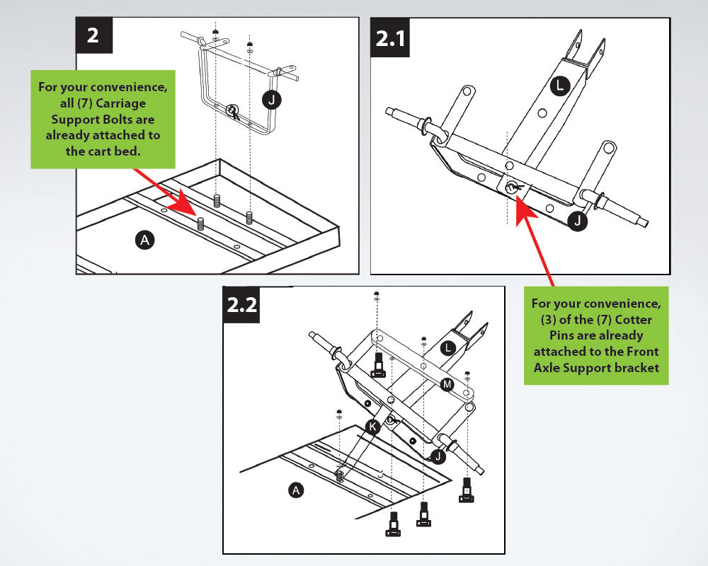
a. Attach the front axle support (J) to the cart bed (A) by using two carriage support bolts which are welded onto the bed, and two 8mm washers (FF) and two 8mm lock nuts (GG) See figure 2.

b. Attach the yoke (L) to the front axle support (J) by using the retainer washer (MM) and cotter pin (L). See figure 2.1

c. Attach the center front axle brace (K) and yoke (L) to the front axle support (J) by using long steering bolts (OO), 6 mm washer (QQ) and 6 mm lock nuts (PP). See figure 2.2

d. Attach the steering link connector (M) to the front axle support (J) and yoke (L) by using three short steering bolts (NN), 6mm washers (QQ) and 6 mm lock nuts (PP). See figure 2.2
NOTE: Leave at least one full turn on each bolt connection to allow for smooth steering operation.

3. Wheel Assembly

a. Place the wheels (F) onto the ends of the front and rear axle supports.

b. Insert a 12 mm washer (HH) and a Cotter Pin (LL) onto the end of each wheel. See figure 3.

c. Put the axle cap (KK) into the end of the rear axle.

3. Wheel Assembly

a. Place the wheels (F) onto the ends of the front and rear axle supports.

b. Insert a 12 mm washer (HH) and a Cotter Pin (LL) onto the end of each wheel. See figure 3.

c. Put the axle cap (KK) into the end of the rear axle.

3. Wheel Assembly

a. Place the wheels (F) onto the ends of the front and rear axle supports.

b. Insert a 12 mm washer (HH) and a Cotter Pin (LL) onto the end of each wheel. See figure 3.

c. Put the axle cap (KK) into the end of the rear axle.

4. Handle Assembly

a. Remove the large pin (JJ) from the plastic coupling (N).

b. Insert the end of the pull handle (O) into the plastic coupling (N). NOTE: Make certain the holes in the pull handle are aligned with the holes in the plastic coupling.

c. Place the pull handle (O) and plastic coupling (N) assembly into the yoke (L).

d. Align the holes in the pull handle and plastic coupling with the holes on the yoke.

e. Insert the large pin (JJ) through the aligned holes and secure the connection with a washer (FF) and a lock pin (CC). See figure 4.

5. Final Cart Assembly

a. After checking all hardware is fully tightened, turn fully assembled cart over.

5b. Rubber Mat Assembly

a. Place the REMOVABLE RUBBER MAT (P) onto the CART PLATFORM (A). The mat can be removed if not needed, at any time.

5c. Tire Inflation

a. Before any attempts to use or operate the cart, check air pressure of each tire.
b. If additional inflation is needed, use a hand-operated air pump, ONLY.
c. Do not exceed 30 PSI as damage to the tires and/or personal injury could result.

Care & Maintenance

• Check for loose fasteners before use.
• At the beginning of each season, lubricate the pivot bolt and bearings with light machine oil.
• Grease the wheel bearings periodically, using general purpose grease.
• Check tire pressure regularly and inflate if needed. Use a hand-operated air pump, ONLY. Never overinflate tires.
• Cover your cart, or store indoors, in a cool, dry place when not in use.


Other Cart Instructions

Other Cart Instructions

Other Cart Instructions

We're Here to Help

Let's Eliminate the Guesswork

Ray's Favorites

Explore Ray's favorite items, and some of our most popular solutions for your yard

Find the perfect product for your exact yard.

Right here. Right now.